
Check valves : calculate the minimum velocity for full opening, step by step calculation guide
Follow us on Twitter

Question, remark? Contact us at contact@myengineeringtools.com
1. Check valves
2. Check valves noise and vibration
3. Step by Step calculation of minimum pipe velocity for full disc lift
4. Interactive Minimum Velocity Calculator (#calc-app)
5. Check valve minimum velocity Excel calculator
1. Check valves
Check valves are ubiquitous in piping Engineering, they are used to ensure that the flow of fluid can happen in a single direction. There are different designs that can be chosen depending on the application.
At its core, a check valve acts as a one-way gate for fluid flow. It allows unrestricted flow in the desired direction while automatically closing to prevent any backflow. This is achieved through a closing element, typically a disc, ball, or flap, that opens and closes in response to the pressure differential across the valve. This simple yet effective mechanism ensures that the fluid travels in the intended direction, preventing potentially detrimental consequences.
2. Check valves noise and vibration
1. Pressure drop
2. Reynolds Number
3. Pressure drop K coefficients
4. Churchill equation
5. Moody diagram
Check valves can present several issues for factories. One of the most common issues is to have a noisy check valve which is quickly getting worn out. One of the reasons for having a noisy check valve is that it opens and closes very quickly; this can happen if the fluid velocity is not high enough to keep the plug or disc of the check valve fully opened.
It is thus key to design the check valve so that the flow through the valve is above the minimum pipe velocity for full disc lift.
3. Step by Step calculation of minimum pipe velocity for full disc lift of check valves
3.1 Step 1 : select a check valve
There are different kinds of common check valves:
- Swing check valves
- Lift check valves
- Tilting disc check valves
- Stop check valves
- Foot valves (special types)
3.2 Step 2 : Get the coefficient of the check valve
Check valves are given a coefficient C that is used in calculating the minimum velocity. The C coefficients for different check valve designs can be found in our database and the calculator below.
3.3 Step 3 : Get the format of velocity calculation for the design studied
The minimum velocity can be calculated in one of two ways based on physical configurations:
or
With:
\(v_{\text{min}}\) = minimum fluid velocity to keep the check valve open (m/s or ft/s)
\(C\) = valve flow coefficient
\(\beta = d_1/d_2\)
\(d_1\) = valve opening diameter (mm or in)
\(d_2\) = pipe internal diameter (mm or in)
\(\rho\) = volumetric mass (density) of the fluid (\(\text{kg/m}^3\) or \(\text{lb/ft}^3\))
\(\overline{V} = \frac{1}{\rho}\) = specific volume of the fluid (\(\text{m}^3/\text{kg}\) or \(\text{ft}^3/\text{lb}\))
3.4 Step 4 : Calculate the minimum velocity to keep the check valve fully open
Replace in the chosen formula the parameters \(C\), \(\beta\), and \(\rho\) by their respective design values.
💡 PLANT ENGINEERING RULES OF THUMB:
• Never Size Check Valves on Line Size Alone: Sizing a check valve solely based on existing pipe diameter is the leading cause of low-velocity chattering and premature seat degradation. If required, use concentric reducers to size the valve smaller than the main line.
• Minimizing Valve Chattering: To prevent fatigue failures on the hinge pin, ensure that the design normal flow velocity is at least 20% to 30% higher than the calculated \(v_{\text{min}}\).
• Velocity Limits: Fluid velocities exceeding 3.0 m/s (10 ft/s) for liquids should be limited to avoid rapid erosion and unacceptable hydraulic pressure drops.
4. Interactive Check Valve Minimum Velocity Sizing Tool
📊 Sizing & Hydrodynamic Analysis Results:
5. Check valve minimum velocity Excel calculator
How to calculate the minimum velocity to keep a check valve fully open?
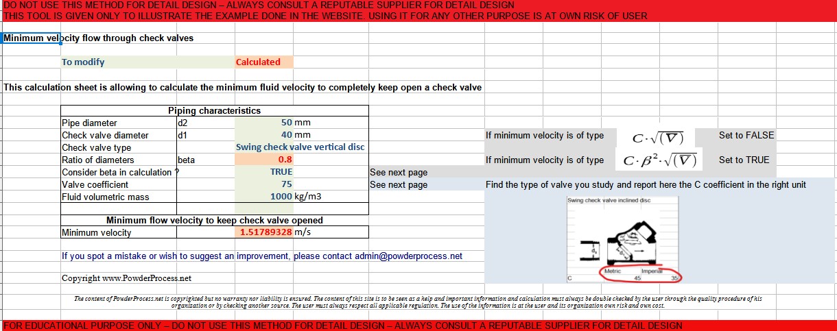
You can access an Excel calculation tool to calculate the minimum fluid velocity in a pipe required to keep a check valve fully open: Check valve minimum fluid velocity Excel calculation tool (click here)
Warning: this calculator is provided to illustrate the concepts mentioned on this webpage; it is not intended for detailed design. It is not a commercial product, and no guarantee is given on the results. Please consult a reputable designer for all detailed design you may need.
Source: Rules of Thumb for Chemical Engineers, Hall, Elsevier