
Pump Power Calculator & Sizing Equations
Definition, Equations, and Sizing of Pump Hydraulic Power, Shaft Power, and Installed Power
Follow us on Twitter

Question, remark ? Contact us at contact@myengineeringtools.com
1. Definition
What is pump hydraulic power? What is pump shaft power?
Two distinct power ratings are associated with a centrifugal or positive displacement pump: the hydraulic power and the shaft power.
In order to size the electric motor or driver properly, it is necessary to determine the exact power that must be transmitted to the pump shaft. The shaft power depends directly on the hydraulic power (the useful work imparted to the liquid) and the total pump efficiency, which accounts for internal hydraulic friction, leakage, and mechanical bearing/seal losses.
The shaft power is also frequently called the absorbed power or brake power ($P_{\text{brake}}$). The pump efficiency ($\eta$) is provided by the manufacturer as a function of operating capacity and can be read directly from the pump characteristic curve.
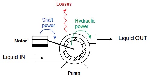
Figure 1 : Pump shaft power vs. hydraulic power schematic
⚡ Interactive Pump Power Calculator
2. Calculation of Hydraulic and Shaft Power
How to calculate the pump hydraulic power?
The hydraulic pump power calculation is derived from the volumetric flow rate, the total dynamic head, and the liquid density. In metric process engineering units, the fundamental equation is expressed as:
\[ P_{\text{hydraulic}} = \frac{Q \times H \times \rho}{367} \]

Equation 1 : Pump Hydraulic Power Equation
With:
\(Q\) : Pump capacity in \(\text{m}^3/\text{h}\)
\(H\) : Total dynamic pump head in \(\text{m}\)
\(\rho\) : Liquid density in \(\text{kg/l}\) (or \(\text{kg/dm}^3\))
\(P_{\text{hydraulic}}\) : Hydraulic Power in kW
Note on constants: The factor 367 originates from standard unit conversions (\(3600 \text{ s/h} / 9.81 \text{ m/s}^2 \approx 366.97\)) to directly yield the power output in kilowatts (\(\text{kW}\)).
How to calculate the pump shaft power?
The pump shaft power is also called the absorbed power or brake power. It represents the mechanical power that must be supplied to the pump coupling to achieve the desired head and flow rate. Because no pump has 100% efficiency, shaft power is always greater than hydraulic power:
\[ P_{\text{shaft}} = \frac{P_{\text{hydraulic}}}{\eta} \]

Equation 2 : Pump Shaft Power Equation
With:
\(P_{\text{shaft}}\) = Pump shaft / absorbed power in \(\text{kW}\)
\(P_{\text{hydraulic}}\) = Pump hydraulic power in \(\text{kW}\)
\(\eta\) = Pump efficiency (fraction between 0 and 1)
3. Calculation of the Installed Power
The shaft power forms the baseline for selecting the driver or electric motor. However, selecting a motor rated exactly equal to the absorbed shaft power carries significant risk. Additional margins are required to prevent overload during startup from standstill, compensate for motor efficiency, account for fluid viscosity/density swings, and accommodate impellers operating off-design or aging over time.
Pump equipment standards (such as API 610 or ISO 5199) specify typical overdesign design factors for the actual installed power of a pump:
| Shaft Power Range (\(P_{\text{shaft}}\) in kW) | Recommended Installed Power Service Factor |
|---|---|
| < 1 kW | 2.0 to 1.5 (+100% to +50% margin) |
| 1 to 5 kW | 1.5 to 1.2 (+50% to +20% margin) |
| 5 to 50 kW | 1.2 to 1.15 (+20% to +15% margin) |
| > 50 kW | 1.10 (+10% margin) |
4. Step-by-Step Example of Pump Power Calculation
Problem Statement: A centrifugal pump is required to deliver \(100 \text{ m}^3/\text{h}\) of water at \(2 \text{ bar g}\) and \(20^\circ\text{C}\) from a feed vessel at atmospheric pressure. The pump inlet and discharge piping both have a nominal diameter of DN100. The pump manufacturer's curve indicates an efficiency of 75% (\(\eta = 0.75\)). Calculate the total dynamic head, hydraulic power, absorbed shaft power, and recommended motor installed power.
STEP 1: Calculate the pump dynamic head
Assuming incompressible flow and equal suction/discharge line diameters, velocity head terms cancel out:
\[ H = \frac{(p_d - p_s) \times 10.2}{d} + \frac{u_d^2 - u_s^2}{2g} \]H = (pd-ps)*10.2/d+(ud2-us2)/(2g)
With water density \(d = 0.998 \text{ kg/l}\) at \(20^\circ\text{C}\):
\(H = \frac{(2 - 0) \times 10.2}{0.998} = 20.44 \text{ m}\)
STEP 2: Calculate the hydraulic power
Applying Equation 1:
\(P_{\text{hydraulic}} = \frac{100 \times 20.44 \times 0.998}{367} = 5.56 \text{ kW}\)
STEP 3: Calculate the shaft power
Dividing hydraulic power by the 75% efficiency factor:
\(P_{\text{shaft}} = \frac{5.56}{0.75} = 7.41 \text{ kW}\)
STEP 4: Calculate the installed motor power
For a shaft power in the range of 5 to 50 kW, a margin factor of 1.20 (+20%) is recommended:
\(P_{\text{installed}} = 7.41 \times 1.20 = 8.89 \text{ kW}\) (selecting a standard 9.2 kW or 11 kW IEC motor size).
💡 Industrial Rules of Thumb & Safety Limits for Pump Design
- Suction Velocity Limits: Keep suction line fluid velocity between 0.6 m/s and 1.2 m/s (2–4 ft/s) to maintain adequate Net Positive Suction Head Available (\(\text{NPSH}_a\)) and prevent cavitation.
- Discharge Velocity Limits: Maintain discharge piping velocity between 1.5 m/s and 3.0 m/s (5–10 ft/s) to balance pipe cost against frictional pressure drop.
- End-of-Curve Overload: Centrifugal pumps with non-overloading impellers achieve peak power at high flow rates. Always verify motor power against the maximum flow condition on the pump curve, not just the Best Efficiency Point (BEP).
- Viscosity Derating: When pumping viscous fluids (> 10 cSt), pump efficiency drops rapidly. Use Hydraulic Institute (HI) correction charts to derate head, flow, and efficiency before calculating shaft power.
5. Pump Power Excel Calculator
Download the free official Excel calculation spreadsheet for offline pump power analysis: Download Excel Pump Power Tool
Warning : this calculator is provided to illustrate the concepts mentioned in this webpage, it is not intended for detail design. It is not a commercial product, no guarantee is given on the results. Please consult a reputable designer for all detail design you may need.
