
Demineralization of water : membrane area calculation step by step
Follow us on Twitter

Question, remark ? Contact us at contact@myengineeringtools.com
1. STEP 1 : Gather data and requirements
2. STEP 2 : Calculate the flux of water through the membrane
3. STEP 3 : Calculate the membrane area required
4. STEP 4 : Calculate permeate and concentrate TDS
5. Membrane area estimation - Calculators
6. Types of Membranes
7. Factors Affecting Membrane Performance
8. Pre-treatment Requirements
9. Energy Consumption
10. Maintenance and Cleaning
11. Applications of Demineralized Water
Demineralization of water is an essential process step for the production of process or drinkable water. Demineralization can be performed thanks to membranes. The methodology below allows process engineers to estimate the membrane surface area required to demineralize a water stream at a given flow rate.
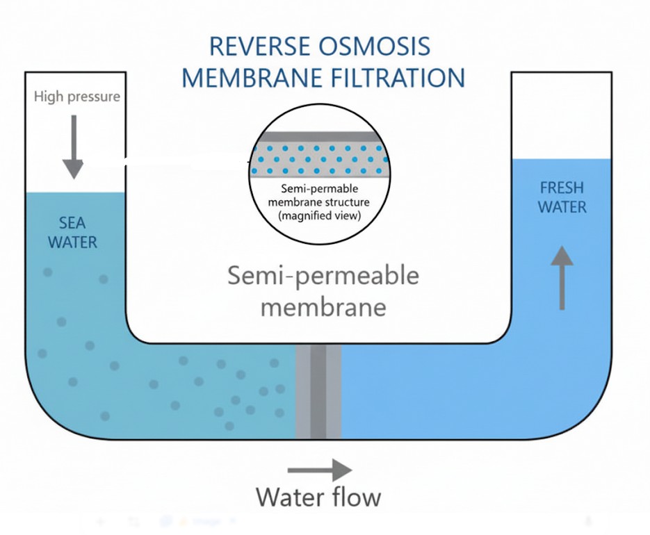
1. STEP 1 : Gather data and requirements
In order to size the membrane required for a demineralization operation, it is necessary to know the characteristics of the infeed water, the characteristics of the membrane to use, and to set some requirements in terms of nominal flowrate and characteristics of the permeate.
Input data:
\(\text{TDS} = C_f\) = feed water total dissolved solid concentration (\(\text{kg/m}^3\))
\(k_w\) = membrane flux rate coefficient (\(\text{s/m}\))
\(k_i\) = membrane mass transfer coefficient (\(\text{m/s}\))
Process requirements:
\(Q_p\) = permeate water flowrate (\(\text{m}^3\text{/s}\))
\(C_{p,\text{max}}\) = permeate maximum total dissolved solid concentration (\(\text{kg/m}^3\))
\(\Delta P_a - \Delta \Pi\) = net operating pressure across the membrane (\(\text{kPa}\))
\(r\) = recovery rate (\(\%\))
\(C_c\) = concentrate total dissolved solid concentration (\(\text{kg/m}^3\))
2. STEP 2 : Calculate the flux of water through the membrane
The flux of water per area unit of membrane can be calculated thanks to the flux rate coefficient of the membrane as well as the operating pressure to which the membrane is submitted. The flux of water can be calculated thanks to the following equation:
\[ F_w = k_w \cdot (\Delta P_a - \Delta \Pi) \]
With:
\(F_w\) = specific flow of water through the membrane (\(\text{kg/m}^2\cdot\text{s}\))
\(\Delta P_a - \Delta \Pi\) = net operating pressure across the membrane (\(\text{kPa}\))
3. STEP 3 : Calculate the membrane area required
Knowing the specific flow through the membrane material considered, as well as the required flow of permeate to handle by the installation, the membrane area can be calculated (it is actually an estimation).
Membrane surface area calculation:
\[ Q_p = F_w \cdot A \]
\[ A = \frac{Q_p}{F_w} \]
With:
\(Q_p\) = permeate water flowrate (\(\text{m}^3\text{/s}\))
\(F_w\) = specific flow of water through the membrane (\(\text{kg/m}^2\cdot\text{s}\))
\(A\) = membrane required filtration area (\(\text{m}^2\))
4. STEP 4 : Calculate permeate and concentrate TDS
The concentration of the permeate can be calculated thanks to the following equation:
\[ C_p = \frac{k_i \cdot A \cdot C_f}{Q_p + k_i \cdot A} \]
With:
\(C_p\) = permeate total dissolved solids concentration (\(\text{kg/m}^3\))
\(k_i\) = membrane mass transfer coefficient (\(\text{m/s}\))
\(A\) = membrane required filtration area (\(\text{m}^2\))
\(\text{TDS} = C_f\) = feed water total dissolved solid concentration (\(\text{kg/m}^3\))
\(Q_p\) = permeate water flowrate (\(\text{m}^3\text{/s}\)), assumed that \(Q_p = r \cdot Q_f\)
\(r\) = recovery rate (\(\%\))
The concentrate concentration in total dissolved solids can be calculated thanks to the following equation:
\[ C_c = \frac{Q_f \cdot C_f - Q_p \cdot C_p}{Q_c} \]
With \(Q_p = r \cdot Q_f\) and \(Q_c = (1 - r) \cdot Q_f\)
💡 Industrial Rules of Thumb & Operational Safety Limits
- Brackish Water RO Flux: Design conservative flux levels between 15 – 25 L/m²/h (8.8 – 14.7 gfd). Operating above 25 L/m²/h accelerates membrane fouling and shortening cleaning intervals (CIP).
- Seawater RO (SWRO) Flux: Maintain lower design flux rates of 8 – 12 L/m²/h (4.7 – 7.0 gfd) due to elevated osmotic pressure and high scaling potential.
- Recovery Limitations: Maximum single-stage recovery is typically capped at 75% – 85% for brackish water to prevent silica and calcium sulfate precipitation without anti-scalants. Single element recovery must not exceed 18%.
- Temperature Flux Correction: Membrane permeability increases by ~2.4% per °C temperature rise (\(\text{TCF} = 1.024^{T - 25}\)). Cold feed water (e.g. 10°C) requires ~40% more membrane area to maintain capacity.
- Design Safety Margin: Always apply a design aging/fouling safety factor of 1.15 – 1.25 to ensure design permeate capacity at the end of 3-year membrane guarantee period.
Top 5 Most Popular
1. Compressor Power Calculation
2. Pump Power Calculation
3. Pipe Pressure Drop Calculation
4. Fluid Velocity in pipes
5. Churchill Correlation (friction factor)
5. Membrane area estimation - Calculators
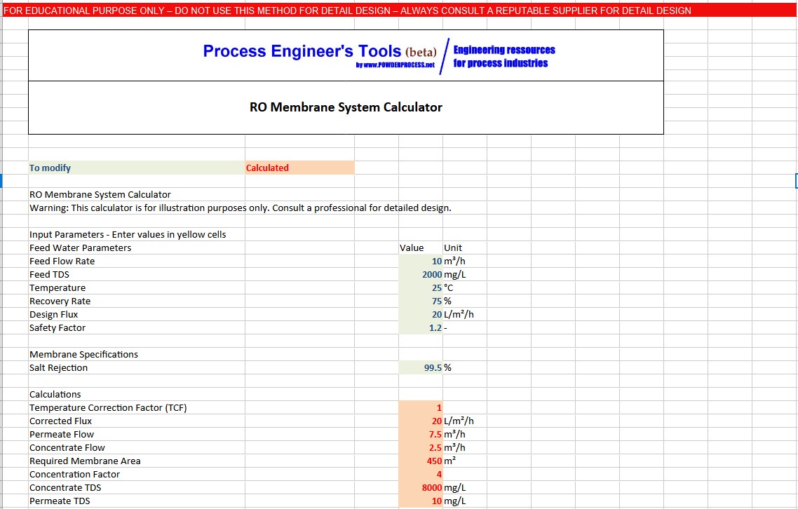
5.1 Excel calculator
You can download the free Excel calculation sheet here: Download RO Membrane System Calculator Excel
5.2 Interactive Online Calculator
RO Membrane Surface Estimation Calculator
Water Demineralization Systems Sizing & Hydrodynamic Analysis
📊 Sizing & Performance Summary
🔢 Calculation Steps & Hydrodynamics
💡 Operational & Engineering Recommendations
Design Guidelines & Reference Parameters
Typical Flux (L/m²/h)
- Brackish Water: 15 - 25
- Seawater: 8 - 12
- Low Pressure: 20 - 35
- Nanofiltration: 20 - 40
Recovery Rates (%)
- Brackish Water: 70 - 85%
- Seawater RO: 35 - 45%
- Industrial Reuse: 60 - 80%
- Max Per Element: <18%
Nominal Salt Rejection
- BW30: 99.5%
- SW30: 99.8%
- LPRO: 99.0%
- Nanofiltration: 96.0%
Operating Envelope
- Temperature: 5 - 45 °C
- pH Range: 2 - 11
- Max Pressure: 600 - 1200 psi
- Feed SDI < 5.0
6. Types of Membranes
Different types of semi-permeable membranes are deployed in water demineralization:
Reverse Osmosis (RO): A leading method for water demineralization that uses dense semi-permeable membranes to remove up to 99.8% of dissolved minerals, salts, and uncharged inorganic species.
Nanofiltration (NF): Used for removing multivalent ions (such as Ca²⁺ and Mg²⁺ hardness) and organic precursors, suitable for partial demineralization and softening.
Ultrafiltration (UF): Porous membrane technology primarily used as a pre-treatment step to remove suspended solids, colloidal silica, macromolecules, and pathogens prior to RO.
Electrodialysis (ED/EDI): Uses electric field potential to drive ions through selective ion-exchange membranes, providing high-purity polish without chemical regeneration.
7. Factors Affecting Membrane Performance
Several physical and chemical factors govern the performance and operational life of demineralization membranes:
Temperature: Higher temperatures lower water viscosity and increase permeate flux, but increase salt passage. Lower temperatures reduce flux, requiring higher net driving pressure.
Operating Pressure: Net driving pressure must overcome systemic osmotic pressure gradient (\(\Delta \Pi\)) to generate design flux without exceeding mechanical burst limits.
pH Levels: Extended exposure to pH levels outside nominal rating (pH 3–10) accelerates hydrolysis of polyamide thin-film active layers.
Fouling and Scaling: Deposition of mineral scale (silica, \(\text{CaSO}_4\), \(\text{CaCO}_3\)) or bio-fouling layer decreases flux rate, increases pressure drop, and elevates permeate salt concentration.
8. Pre-treatment Requirements
Proper feed pre-treatment is paramount to safeguard reverse osmosis elements against premature fouling:
Multi-Media / Cartridge Filtration: Removes particulate suspended matter to keep Silt Density Index (\(\text{SDI}_{15}\)) below 3.0–5.0.
Scale Inhibitor Dosing: Adds polyphosphonate or polycarboxylate anti-scalants to prevent mineral salt crystallization at high recovery rates.
Softening & pH Adjustment: Reduces hardness cations or acidifies feed water to shift carbonate balance away from \(\text{CaCO}_3\) scaling.
De-chlorination: Active chlorine damages polyamide RO active layers rapidly; sodium bisulfite (\(\text{NaHSO}_3\)) or activated carbon beds are mandatory pre-RO.
9. Energy Consumption
Pumping power represents the largest operating expenditure in RO plant operations. Optimization techniques include:
Energy Recovery Devices (ERD): Pressure exchangers and Pelton turbines capture hydraulic pressure energy from the reject concentrate stream, reducing SWRO specific power consumption by up to 60%.
High-Efficiency Variable Speed Pumps: VFD control adapts pump pressure to fluctuating water temperatures and seasonal osmotic variations.
Low-Energy Elements: Modern low-pressure high-permeability polyamide chemistry operates at lower driving pressures for brackish applications.
10. Maintenance and Cleaning
Routine Clean-In-Place (CIP) procedures restore hydraulic performance when normalized permeate flow decreases by 10% or differential pressure increases by 15%:
Low-pH Acid Cleaners: Citric acid or hydrochloric acid formulations remove inorganic scaling (\(\text{CaCO}_3\), metal oxides).
High-pH Alkaline Cleaners: NaOH and surfactant solutions clean bio-fouling, organic foulants, and colloidal clay deposits.
Performance Normalization: Daily tracking of temperature, pressure, and conductivity standardizes flow data to baseline conditions.
11. Applications of Demineralized Water
Demineralized water is critical across major industrial sectors:
Pharmaceutical Industry: Purified Water (PW) and Water for Injection (WFI) generation.
Electronics & Semiconductors: Ultra-Pure Water (UPW) for microchip wafer rinsing.
Power & Thermal Boilers: High-pressure steam turbine boiler feed water to prevent tube scaling.
Chemical Processing: Reaction solvent water and cooling tower make-up.
FAQ: Demineralization of Water - Membrane Area Calculation
1. What is demineralization of water, and why is it important?
Demineralization is the removal of dissolved mineral salts and ionic species (TDS) from water to produce high-purity industrial process water, boiler feedwater, or potable water. It prevents scale formation, corrosion, and product contamination.
2. What data is required to calculate the membrane area for demineralization?
Required data includes feed water flow rate (\(Q_f\)), Total Dissolved Solids (\(\text{TDS}\)), feed temperature, membrane flux coefficient (\(k_w\)), mass transfer coefficient (\(k_i\)), target recovery rate (\(r\)), and net operating pressure (\(\Delta P_a - \Delta \Pi\)).
3. How is the flux of water through the membrane calculated?
The water flux (\(F_w\)) is calculated via: \[ F_w = k_w \cdot (\Delta P_a - \Delta \Pi) \]
4. How is the required membrane area determined?
Required total membrane filtration area (\(A\)) is calculated by dividing permeate volumetric flow rate (\(Q_p\)) by temperature-corrected design flux (\(F_w\)): \[ A = \frac{Q_p}{F_w} \cdot \text{Safety Factor} \]
5. What is the recovery rate, and how does it affect the process?
Recovery rate (\(r\)) is the volume percentage of feed water recovered as purified permeate (\(r = Q_p / Q_f\)). Increasing recovery reduces waste flow but elevates concentrate TDS and osmotic back-pressure exponentially.
6. How is permeate TDS concentration calculated?
Permeate TDS (\(C_p\)) is calculated using mass transfer kinetics: \[ C_p = \frac{k_i \cdot A \cdot C_f}{Q_p + k_i \cdot A} \] or via nominal salt rejection \(R\): \(C_p = C_f \cdot (1 - R)\).
7. How is concentrate TDS concentration calculated?
Concentrate TDS (\(C_c\)) is derived from overall solute mass balance: \[ C_c = \frac{Q_f \cdot C_f - Q_p \cdot C_p}{Q_c} \]
8. What are typical design flux rates for different water types?
Typical design fluxes are: Brackish Water = 15 – 25 L/m²/h; Seawater RO = 8 – 12 L/m²/h; Low Pressure RO = 20 – 35 L/m²/h; Nanofiltration = 20 – 40 L/m²/h.
9. What are typical recovery rates for different applications?
Brackish water RO: 75% – 85%; Seawater RO: 35% – 45%; Industrial wastewater reuse: 60% – 80%.
10. Are there tools available to estimate membrane area?
Yes, our website offers both an interactive online calculator above and a downloadable free Excel RO Sizing Calculator.
Sources
[Chopey] Handbook of Chemical Engineering calculations, Chopey et al, McGraw Hill, 2004