
Centrifugal compressor : head coefficient, flow coefficient and compression ratio
Follow us on Twitter 
Question, remark ? Contact us at contact@myengineeringtools.com
| Section summary |
|---|
| 1. Performance of an
impeller |
| 2. Head coefficient
of pressure coefficient |
| 3. Flow coefficient |
| 4. Compression ratio
calculation |
1. Performance of an impeller
It is possible to estimate the performance of a centrifugal compressor, in terms of compression ratio or flowrate if the manufacturer has given some information about the impeller, in addition to basic dimensional data : the head coefficient, the flow coefficient and the polytropic efficiency.
This page aims at answering to the following questions : what is the head coefficient ? What is the flow coefficient ? What is the relation between the head and flow coefficient ? How to calculate the compression ratio given by an impeller ?
2. Head coefficient or pressure coefficient
The head coefficient is an adimensional number that is comparing
the polytropic work that one gets during compression to the impeller
tip speed
\[ \mu = \frac{W_p}{u_2^2} \]

Equation 1 : calculation of compressor head coefficient
With
μ = pressure coefficient
Wp = polytropic work in J/kg
u2 = tip speed of the impeller in m/s
⚙️ Practical Plant Engineering Rules of Thumb & Safety Limits
- Typical Head Coefficients: For centrifugal flow impellers, the head coefficient (μ) generally ranges from 0.5 to 0.6. Higher values might indicate more aggressive designs or specific applications.
- Tip Speed Limitations: Impeller tip speed (u2) is often limited by material strength (mechanical integrity) and the Mach number at the blade tip (aerodynamic performance, preventing choking and excessive noise). Typical limits can be around 300-450 m/s for high-speed industrial compressors, but can vary widely. Exceeding sonic velocity at the blade tip can lead to significant performance degradation and vibration.
- Polytropic Work (Wp): This value is dependent on the gas properties and the achieved pressure ratio. For common gases like air, Wp will typically be in the range of 30,000 to 100,000 J/kg for a single stage.
- Input Validation: Ensure all inputs are positive. Zero or negative tip speed would result in division by zero and is physically meaningless.
Order of magnitude of the pressure coefficient :
- Centrifugal flow impeller : 0.5 to 0.6
- Mixed flow impeller : 0.35
- Axial flow impeller : 0.05 to 0.25
- Peripheral flow impeller : 1.8
Top 5 Most
Popular
1. Compressor
Power Calculation
2. Pump Power Calculation
3. Pipe Pressure
Drop Calculation
4. Fluid Velocity in pipes
5. Churchill Correlation
(friction factor)
3. Flow coefficient
The flow coefficient is calculated the following way :
\[ \delta = \frac{Q_v}{u_2 \cdot R_2^2} \]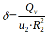
Equation 2 : flow coefficient calculation
With
δ = flow coefficient
u2 = tip speed of the impeller in m/s
R2 = impeller outside radius in m
Qv = compressor flowrate in m3/s
⚙️ Practical Plant Engineering Rules of Thumb & Safety Limits
- Typical Flow Coefficients: For centrifugal impellers, the flow coefficient (δ) typically ranges from 0.04 to 0.2. Mixed-flow impellers can go up to 0.6, while axial flow designs can be much higher (0.8 to 1.2).
- Impeller Radius (R2): The impeller radius significantly impacts both tip speed and the area available for flow. Larger radii at a given RPM mean higher tip speeds.
- Volumetric Flowrate (Qv): This value is highly dependent on the compressor's operating point and the gas density at suction conditions. Ensure consistency with the actual inlet conditions.
- Relation between μ and δ: There's an inverse relationship between the head coefficient (μ) and flow coefficient (δ). Generally, designs optimized for high pressure rise (high μ) tend to have lower flow capacities (lower δ), and vice-versa. This characteristic is often depicted in compressor performance maps.
Order of magnitude of the flow coefficient :
- Centrifugal flow impeller : 0.04 to 0.2 with until 0.6 for mixed flow
- Axial flow impeller : 0.8 to 1.2
- Peripheral flow impeller : 0.04
Note that there is relation in between μ and δ : the lower the flow coefficient, the higher will be the pressure coefficient. The manufacturer can deliver the curve μ=f(δ) to help size the compressor but one must be careful that the relation will change if the gas handled changed or if the speed of the compressor varies beyond a certain limit
4. Compression ratio calculation
Thanks to the head coefficient it is possible to calculate which compression ratio will be given by an impeller. This calculation is based on the definition of the pressure coefficient and the definition of the polytropic work.
\[ \tau = \left[ \frac{(k-1) \cdot \mu \cdot u_2^2 \cdot M}{k \cdot \eta_p \cdot R \cdot T_{suction}} + 1 \right]^{\frac{k \cdot \eta_p}{k-1}} \]
Equation 3 : compression ratio calculation
With
τ = compression ratio
k = isentropic coefficient
μ = pressure coefficient
u2 = tip speed of the impeller in m/s
M = molar mass of the gas
ηp = polytropic coefficient
R = ideal gas constant
Tsuction = suction temperature in K
⚙️ Practical Plant Engineering Rules of Thumb & Safety Limits
- Isentropic Coefficient (k): Also known as the heat capacity ratio (Cp/Cv). This value is gas-specific; e.g., for air it's around 1.4, for methane 1.3, for CO2 1.3. Accurate 'k' values are crucial for correct compression ratio calculation.
- Polytropic Efficiency (ηp): Represents how effectively the compressor converts input power into useful compression work. Typical values for industrial centrifugal compressors range from 0.70 to 0.85. Higher efficiencies are desirable for reduced energy consumption.
- Molar Mass (M): This is gas-specific. For air, it's approximately 28.97 g/mol. Heavier gases generally require more work for a given compression ratio.
- Suction Temperature (Tsuction): Must be in absolute units (Kelvin or Rankine). Colder suction temperatures generally result in higher compression ratios for the same polytropic work input.
- Compression Ratio per Stage: For a single centrifugal impeller, the compression ratio (τ) is typically limited to 3-5. Achieving very high ratios in a single stage can lead to very high discharge temperatures and mechanical stresses. Multi-stage compressors are used for higher overall pressure ratios.
Note that the compression ratio is actually independent from the
suction pressure.