
Plug Flow Reactors (PFR) : mass balance expression
Follow us on Twitter 
Question, remark ? Contact us at contact@myengineeringtools.com
1. Plug Flow Reactors
2. Plug Flow reactor in steady state : mass balance
3. Plug flow reactor : no volumetric flow variation
Plug flow reactors (PFR) are a very specific type of reactor, different from agitated vessels for example. Instead of having the fluids in relatively large tank, the fluid is pushed in a reactor having a cylindrical shape which can be as simple as a pipe. This page focusing in applying the general mass balance equations to PFR reactors.
1. Plug Flow Reactors
A Plug Flow Reactor is a continuous reactor equipped with an inlet of reactants and an outlet of the content of the reactor which are done continuously during the operation of the reactor.
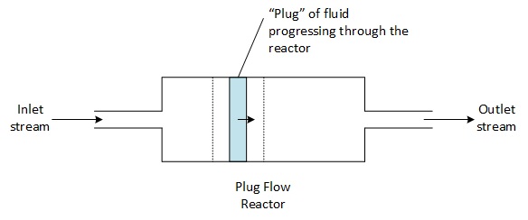
A plug flow reactor has no agitator, it has a cylindrical shape which allows the fluid to progress with a minimal amount of back mixing, as a consequence all the particles of fluid that enter the PFR have the same residence time. The plug flow reactor can indeed be considered as a succession of thin slices of fluid, constituting a small batch reactor, perfectly stirred within the slice, which moves ahead in the reactor as piston.
The general mass balance equation can then be expressed the following way for one of the slices of fluids in the reactor :
\[ \text{Inlet} = \text{Outlet} + \text{Consumption} + \text{Accumulation} \]
The units of each component of the expression is a material flowrate : mol/s for instance.
2. Plug Flow reactor in steady state : mass balance
The study is done on a small slice of the reactor, of volume \( dV \). This small slice of fluid behaves like a small CSTR reactor : it is very small and thus assumed perfectly agitated, and it is in steady state. The mass balance for the volume \( dV \) can then be done, using the general mass balance equation :
\[ F_{A,i} = F_{A,o} + r'_A \cdot dV + \frac{dn_A}{dt} \]
With :
\( F_{A,i} \) : the molar flow at the inlet of the slice \( dV \)
\( F_{A,o} \) : the molar flow at the outlet of the slice \( dV \)
Top 5 Most Popular
1. Compressor Power Calculation
2. Pump Power Calculation
3. Pipe Pressure Drop Calculation
4. Fluid Velocity in pipes
5. Churchill Correlation (friction factor)
As the small reactor of volume \( dV \) is in steady state, we can assume that : \[ \frac{dn_A}{dt} = \frac{dn_B}{dt} = \frac{dn_C}{dt} = \frac{dn_D}{dt} = 0 \]
\[ F_{A,i} = F_{A,o} + r'_A \cdot dV \]
It is possible to express \( F_{A,o} = F_{A,i} + \left(\frac{dF_{A,i}}{dV}\right) \cdot dV \) as the flow of reactant A is expected to vary just a little bit from the inlet flow in the volume \( dV \).
\[ F_{A,i} = F_{A,i} + \left(\frac{dF_{A,i}}{dV}\right) \cdot dV + r'_A \cdot dV \]
It allows to calculate the general expression of the reaction rate of consumption of the reactant A in a plug flow reactor as :
\[ r'_A = -\frac{dF_{A,i}}{dV} \]
Considering the reaction \( A + B \rightarrow C + D \), the other reaction speed can be expressed, for a slice of volume \( dV \) in the piston reactor, as :
\[ r'_B = -\frac{dF_{B,i}}{dV} \]
\[ r_C = \frac{dF_{C,i}}{dV} \]
\[ r_D = \frac{dF_{D,i}}{dV} \]
3. Plug flow reactor : no volumetric flow variation
In case the volumetric flow within the reactor stays constant (\( Q_i = Q_o = Q \) at any point in the reactor), the reaction speeds above can be simplified and expressed as a function of the concentration.
\[ F_{A,i} = Q \cdot [A]_i \]
\[ r'_A = -\frac{dF_{A,i}}{dV} = -Q \cdot \frac{d[A]_i}{dV} \]
In this expression, the ratio \( dV / Q \) can be identified : it is the time required by the particles to go through the small volume \( dV \). Integrated over the whole reactor, it gives \( \tau \) the residence time of the particles in the plug flow reactor, thus \( dV / Q = d\tau \).
The reaction speed can then be expressed as :
\[ r'_A = -\frac{d[A]_i}{d\tau} \]
Case of a reaction with known stoichiometry
In case the reaction stoichiometry is known, the reaction speed above can just be written by adding the stoichiometric coefficient \( \nu_A \).
\[ r_A = \frac{1}{\nu_A} \cdot \frac{d[A]_i}{d\tau} \]
\[ \frac{d[A]_i}{d\tau} = \nu_A \cdot r_A \]
The stoichiometric coefficient is positive for a product of the reaction and negative for a reactant that is consumed.
⚡ Interactive Plug Flow Reactor (PFR) Calculator
Process & Kinetic Inputs
Calculation Results
💡 Industrial Engineering Rules of Thumb for PFR Sizing
- Ideal Plug Flow Criterion: To ensure plug flow behavior and minimize axial backmixing, the length-to-diameter ratio (\(L/D\)) of tubular reactors should typically exceed 50:1 (preferably \(> 100:1\)), or Reynolds numbers should be kept in high turbulent flow (\(Re > 4000\)).
- PFR vs CSTR Efficiency: For standard positive-order kinetics, a PFR is always more volume-efficient than a CSTR. For high conversions (\(X_A > 90\%\)), a single CSTR can require 5 to 10 times more volume than an equivalent PFR.
- Pressure Drop & Velocity Limits: High fluid velocities increase turbulence (improving radial heat transfer and plug flow kinetics) but dramatically scale pressure drop (\(\Delta P \propto u^2\)). Maintain liquid tube velocities between 1.0 and 2.5 m/s to prevent excessive erosion or pumping power losses.
- Thermal Runaway Safety: Highly exothermic reactions in PFRs can develop steep axial temperature peaks (hot spots). Multi-tubular heat-exchanger reactors with high heat transfer surface area per unit volume are standard for handling strong thermal loads.