
Semi-Batch Reactors: Mass Balance Expression & Kinetics Modeling
Follow us on Twitter

Question, remark? Contact us at contact@myengineeringtools.com
- Semi-Batch Reactor Overview
- Mass Balance of Isothermal, Perfectly Stirred Semi-Batch Reactors
- Stoichiometry and Reaction Rates
- Volume Change Considerations
- Practical Applications and Examples
- Common Challenges and Solutions
- Optimization Techniques
- Example Calculation: Mass Balance in a Semi-Batch Reactor
- Interactive Isothermal Kinetic Simulator (Calculator)
Semi-batch reactors are often presented in academic environments as highly specific niche vessels. It turns out they are exceptionally common in process industries, offering key advantages in terms of control of chemical reactions (e.g., slowly dosing a limiting reactant to control highly exothermic runs or minimize competitive side reactions). This page focuses on formulating and applying the general mass balance equations to transient semi-batch operations.
1. Semi-Batch Reactor Overview
A semi-batch reactor is physically a batch reactor equipped with either a continuous feed stream (inlet) or a continuous product withdrawal stream (outlet).

Both modes are industrial realities. For simplicity in kinetic modeling, the case of a semi-batch reactor with a continuous inlet of reactant is detailed below.
The system is initialized with a primary batch charge of reactants (except one). When the feed valve is opened, the transient reaction sequence begins. Charging stops once the target stoichiometric quantity has been delivered. Once the design conversion is reached, the reaction is terminated and the vessel is drained.
With the outlet valve closed during feeding, the dynamic mass balance equation simplifies as follows:
Inlet = Outlet + Consumption + Accumulation
Inlet = 0 + Consumption + Accumulation
Units for each component in these expressions are dynamic material molar flowrates (e.g., \(\text{mol/s}\) or \(\text{lb-mol/h}\)).
In the physical models below, the semi-batch reactor is assumed to be:
- Perfectly stirred (ideal mixing, spatial uniformity)
- Isothermal (active temperature feedback control)
2. Isothermal, Perfectly Stirred Semi-Batch Reactor: Mass Balance Equations
Let's assume a generic reaction system of the form \(A + B \rightarrow C + D\). Reactant B is charged initially to the vessel at \(t = 0\), while Reactant A is dosed continuously starting at \(t > 0\).
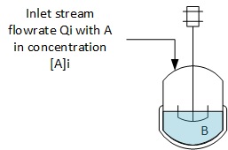
Perfect mixing guarantees concentration uniformity throughout the volume. Molar rates of production and consumption can be expressed directly as the product of the homogeneous reaction rate and the instantaneous fluid volume \( (r \cdot V) \).
The individual component balances (where \(r'\) denotes a rate of consumption and \(r\) denotes a rate of formation) are written as:
Reactant A:
\[ F_{A,in} = 0 + r'_A \cdot V + \frac{dn_A}{dt} \implies Q_i \cdot [A]_i = r'_A \cdot V + \frac{dn_A}{dt} \]Reactant B:
\[ 0 = 0 + r'_B \cdot V + \frac{dn_B}{dt} \implies r'_B = -\frac{1}{V} \frac{dn_B}{dt} \]Product C:
\[ 0 = 0 - r_C \cdot V + \frac{dn_C}{dt} \implies r_C = \frac{1}{V} \frac{dn_C}{dt} \]Product D:
\[ 0 = 0 - r_D \cdot V + \frac{dn_D}{dt} \implies r_D = \frac{1}{V} \frac{dn_D}{dt} \]The system of differential reaction speeds is summarized as:
\[ r'_A = \frac{Q_i \cdot [A]_i - \frac{dn_A}{dt}}{V} \] \[ r'_B = -\frac{1}{V} \frac{dn_B}{dt} \] \[ r_C = \frac{1}{V} \frac{dn_C}{dt} \] \[ r_D = \frac{1}{V} \frac{dn_D}{dt} \]
Top 5 Most Popular Calculations
1. Compressor Power Calculation
2. Pump Power Calculation
3. Pipe Pressure Drop Calculation
4. Fluid Velocity in Pipes
5. Churchill Friction Factor
3. Stoichiometry and Reaction Rates
For the single-phase chemical reaction \(A + B \rightarrow C + D\), stoichiometry dictates that the consumption of reactants and production of products proceed in equal molar proportions. Assuming stoichiometric coefficients of unity, the rates are constrained by:
\[ r'_A = r'_B = r_C = r_D \]These relationships are essential for solving the system of ordinary differential equations (ODEs) describing transient concentration and temperature trajectories.
4. Volume Change Considerations
In semi-batch reactors, fluid volume is dynamic and increases according to the volumetric feed rate:
\[ \frac{dV}{dt} = Q_i \]Integrating with respect to time for a constant-density fluid yields the instantaneous volume \(V(t)\):
\[ V(t) = V_0 + Q_i \cdot t \]Since the concentrations are defined as \([J] = n_J / V\), the dynamic volume must be directly incorporated into the accumulation terms:
\[ \frac{d(n_A)}{dt} = \frac{d([A] \cdot V)}{dt} = V \frac{d[A]}{dt} + [A] \frac{dV}{dt} = V \frac{d[A]}{dt} + [A] \cdot Q_i \]5. Practical Applications and Examples
Semi-batch vessels are widely specified across the chemical process industries (CPI) for operations demanding strict process window boundaries:
- Controlled Polymerizations: Adding monomers gradually to narrow the molecular weight distribution and regulate heat release.
- Fine Organics Synthesis: Limiting reactant concentration to favor target reactions over competitive side reactions.
- Pharmaceutical Formulations: Safe dosing of highly reactive materials to manage heat loads in small-to-medium vessels.
⚠️ Plant Engineering Rules of Thumb & Safety Limits
- Overfill Margin: Design maximum reactor liquid volumes to not exceed 80% to 85% of the total vessel capacity to permit appropriate headspace and vapor disengagement.
- Feed-Controlled Exotherms: Run reactions in the "feed-controlled" regime (reaction rate \(\gg\) feed rate) to prevent accumulation of unreacted feed, which can lead to runaway reactions if cooling fails.
- Stirrer Location: Ensure feed inlet lines inject reactant directly into the high-shear region of the impeller to minimize concentration hotspots.
6. Common Challenges and Solutions
- Runaway Thermal Hazards: Solved by interlock controls matching feed pump rates to the maximum cooling duty of the jacket.
- Localized Hotspots: Solved by using high-efficiency dual impellers (axial/radial) and internal baffles.
- Changing Heat Transfer Area: As volume rises, jacket contact area increases. Controllers must dynamically tune PID settings.
7. Optimization Techniques
- Non-Linear Dosing Profiles: Optimizing the volumetric feed trajectory \(Q_i(t)\) to maximize space-time yield.
- Model Predictive Control (MPC): Combining temperature sensors with dynamic kinetics models to run at peak capacity limits.
8. Example Calculation: Mass Balance in a Semi-Batch Reactor
8.1. Define the Reaction and Reactor Conditions
Consider the model reaction \(A + B \rightarrow C + D\) under the following baseline conditions:
- Initial Reactor Volume (\(V_0\)): \(100\text{ L}\)
- Initial Moles of B (\(n_{B0}\)): \(50\text{ mol}\)
- Feed Concentration of A (\([A]_i\)): \(2\text{ mol/L}\)
- Volumetric Flow Rate (\(Q_i\)): \(10\text{ L/h}\)
- Reaction Rate Constant (\(k\)): \(0.05\text{ L/(mol}\cdot\text{h)}\)
8.2. Mass Balance ODE System
\[ \frac{dn_A}{dt} = Q_i \cdot [A]_i - k \frac{n_A n_B}{V(t)} \] \[ \frac{dn_B}{dt} = -k \frac{n_A n_B}{V(t)} \] \[ \frac{dn_C}{dt} = \frac{dn_D}{dt} = k \frac{n_A n_B}{V(t)} \] \[ V(t) = 100 + 10 \cdot t \]The integrated concentration profiles calculated using a numeric timestep of \(\Delta t = 1.0\text{ h}\) are detailed in the historical verification table below:
| Time (h) | Volume (L) | Moles of A (mol) | Moles of B (mol) | Moles of C (mol) | Moles of D (mol) | [A] (mol/L) | [B] (mol/L) |
|---|---|---|---|---|---|---|---|
| 0.0 | 100.0 | 0.00 | 50.00 | 0.00 | 0.00 | 0.000 | 0.500 |
| 1.0 | 110.0 | 19.77 | 49.77 | 0.23 | 0.23 | 0.180 | 0.452 |
| 2.0 | 120.0 | 39.14 | 49.14 | 0.86 | 0.86 | 0.326 | 0.409 |
| 3.0 | 130.0 | 58.19 | 48.19 | 1.81 | 1.81 | 0.448 | 0.371 |
| 4.0 | 140.0 | 77.00 | 47.00 | 3.00 | 3.00 | 0.550 | 0.336 |
| 5.0 | 150.0 | 95.62 | 45.62 | 4.38 | 4.38 | 0.637 | 0.304 |
| 6.0 | 160.0 | 114.11 | 44.11 | 5.89 | 5.89 | 0.713 | 0.276 |
| 7.0 | 170.0 | 132.49 | 42.49 | 7.51 | 7.51 | 0.779 | 0.250 |
| 8.0 | 180.0 | 150.80 | 40.80 | 9.20 | 9.20 | 0.838 | 0.227 |
| 9.0 | 190.0 | 169.08 | 39.08 | 10.92 | 10.92 | 0.890 | 0.206 |
| 10.0 | 200.0 | 187.33 | 37.33 | 12.67 | 12.67 | 0.937 | 0.187 |